Arduino Dice
An Arduino based circuit to simulate a dice using LEDs.
Hold down the button, to throw the dice. While the button is pressed, you will see the dice spinning through random values. Take you finger off the button, and it stops.
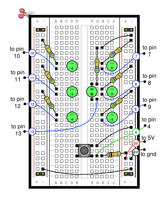
Breadboard Diagram

Notes
Bend both the legs of the center LED, so that it connects as shown. (We want the LED to line up nicely to make the dice pattern, but it won't work if we connect it to the same rows as the LED on its right).
The value of the resistors will depend on the type of leds you are using. See the LED Resistor page for more details.
Key
Code
/*
  Simulates a dice using 7 LEDS.
*/

/*
  Lets number each of the LEDS from 0 to 6 like so :

  0     4

  1  3  5

  2     6

  For each side of the dice, which LEDS need turning on?
  A number 1 needs to light LED 3
  A number 2 needs to light LEDS 2 and 4

  the following array stores this information, as well as an extra item at the beginning for zero (where no LEDS are on).
  Note that a value of "-1" means "the end", so each number must have -1 at the end.
*/
int diceData[7][7] = { {-1}, {3,-1}, {2,4,-1}, {0,3,6,-1}, {0,2,4,6,-1}, {0,2,3,4,6,-1}, {0,1,2,4,5,6, -1} };

/*
So far we have used the numbers 0 to 6 to number the LEDs, but we haven't said which pins to use on the Arduino.
We could assume they are connected to pins 0 to 6, but that would be inflexible, because we may want to use those
for something else.
The solution is to have a list of pins to use, and here it is :
*/
int dicePins[7] = {10, 11, 12, 13, 7, 8, 9};
/*
In the above the LED number zero is connected to pin 10, LED number 1 is connected to pin 11 etc.
*/


// The pins to set high for each number 0..6
// -1 indicates the end of the sequence. Without that, we have no way to know the length of each.

// This pin is connected to a button, when pressed the dice runs through random numbers, and stops when released.
int buttonPin = 4;

void setup() {
  for ( int n = 0; n <= 6; n ++ ) {
    pinMode( dicePins[ n ], OUTPUT );
  }
  pinMode( buttonPin, INPUT );

  // Run through a quick sequence of 1 to 6 and then back down to zero.
  // test the LEDs are working ok.
  for ( int n = 1; n <=6; n ++ ) {
    dice( n );
    delay(200);
  }
  for ( int n = 5; n >= 0; n -- ) {
    dice( n );
    delay(200);
  }
}

void loop() {

  // Is the button pressed?
  if ( ! digitalRead( buttonPin ) ) {
    dice( random( 6 ) + 1 ); // Pick a number from 1 to 6, and display it on the leds
  }
  delay( 50 ); // a tenth of a second delay

}

/*
  Displays a number dice-style for the number passed in.
*/
void dice( int number /* 0..6 */ ) {
  // Turn all LEDs off
  for ( int pin = 0; pin <= 6; pin ++ ) {
    digitalWrite( dicePins[ pin ], LOW );
  }

  // Turn on the required LEDs
  for ( int i = 0; i < 6; i ++ ) {
    // Find out the LED number to light. This will be in the range 0..7. Note this is NOT the pin number.
    int ledNumber = diceData[ number ][ i ];
    if ( ledNumber == -1 ) {
      // We've got to the end of the list of LEDs to light, so get out of here, we are done!
      return;
    }

    // Look up the
    int pin = dicePins[ ledNumber ];

    // Light the LED
    digitalWrite( pin, HIGH );
  }
}
Possible Improvements
We could achieve the same result, using less pins on the Arduino. We don't really need each LED to be independent. For example, the opposite corners of the dice are always on at the same time, therefore we could design a circuit where opposite corners are wired into a single pin on the Arduino. So instead of seven pins, we could use just 4 (one for the middle, two for the corners, and one for the remaining two LEDs).
So, if we wanted to show two dice, that would use up 8 pins.
That's not bad, but what if we want 5 dice (Yahtzee anybody?). That would require 4 x 5 pins - too many!
The solution is to use shift registers. Using shift registers, we could, in theory, display hundreds of dice using only 3 pins on the Arduino.
If you want help creating such a circuit, Contact me, and I'll find the time to draw the improved circuits and write the program too.


