Matt LEDs
An Arduino based circuit to write out the word "Matt" usings LEDs. The LEDs are turned on in various sequences.
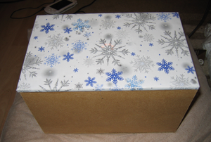
The LEDs were wired onto an MDF board, and then covered by another MDF board, with holes drilled into it the same size (and in the same position) as the LEDs. It was then covered in christmas wrapping paper. The net result is a plain looking box when the LEDs are off, but the LEDs can easily shine through the thin paper. Magic! This double thickness MDF board is used as the lid of a box (also made from MDF).
I used these boxes to wrap up Christmas presents for my nephews (both called Matthew) - the present was the Arduino! The box was big enough to house the Arduino, with room to spare for the previous year's gift - a hot glue gun. Yes, I'm trying to turn them into "Maker" geeks.
Photo
On the left is the box with the LEDs off. On the right is a close-up, while the LEDs are all on. It looks a different colour because the camera's flash was turned off.
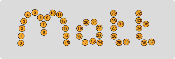
LED Layout

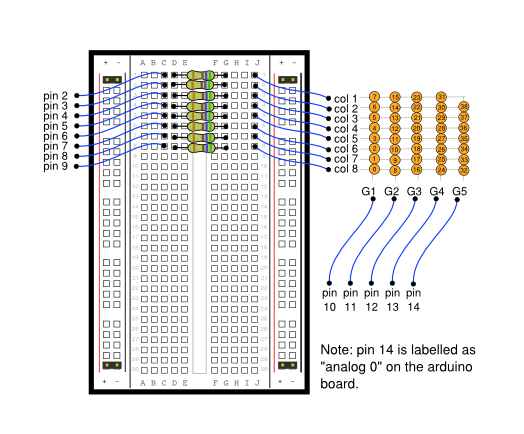
Breadboard Diagram

Notes
The LEDs are wired up, as if in a grid pattern.
The first 8 LEDs' cathodes are wired together, and labelled "1". The next 8 LEDs' cathodes are wired together and labelled "2" etc.
The anodes of LEDs #0, #8, #16, #24, #32 are wired together and labelled "G1". Similarly the anodes of LEDs #1, #9, #17, #25 and #33 are wired together and labelled "G2". etc.
Key
| Symbol | Description | Quantity | Photo |
|---|---|---|---|
 | 560 ohm Resistor | 8 | {{plainthumb(page="resistors.jpg")}} |
 | Amber LED | 39 | {{plainthumb(page="leds.jpg")}} |
Got a Problem?
If 8 LEDs in a line don't work, you've probably got a loose connection on one of the "column" wires (or their resistors).
If 4 or 5 LEDs dotted about the place don't work, you've probably got a loose connection on one of the "group" wires.
There's something weird in the middle of the "M". Matt Robinson's board is wired up wrong :-( Two of the LEDs are wired up the wrong way round. Ooops.
Code
/*
  LED Animation.
  Designed to spell out the word "Matt" using 39 LEDs

  The long pins on LEDs are anodes i.e. connect to "HIGH" (+5V) when lit.
  The short pins on the LEDS are cathodes i.e. connect to "LOW" (Ground).

  The first 8 leds' anodes are all connected together. The next 8 leds' anodes are
  all connected together etc. There are five such groups. The common anode of each
  group are connected to the Arduino to pins 2,3,4,5 and 6, but this can be changed
  by changing the array "groupPins" below.

  The first led in each group have all of their cathodes connected together.
  Similarly the second led in each group have their cathodes connected together etc.
  Each of these are called a "column". There are 8 columns, and are connected to the
  Arduino via a resitor to pins 7.

  We have 5 groups of 8, giving a total of 40 possible leds, but only 39 have been used
  to write out the name "Matt".
*/

#define GROUPS 5 // The number of groups
#define COLUMNS 8 // The number of columns
#define LEDS 39 // The number of LEDs

#define pauseDelay 100 // Number of milliseconds to wait to display each group of leds before moving onto the next.

// Pin Definitions
int groupPins[ GROUPS ] = {10,11,12,13,14};          // An Array defining which pin each groups's anodes are attached to
                                        // (drive HIGH to activate the group)
int columnPins[ COLUMNS ] = {2,3,4,5,6,7,8,9};    // An Array defining which pin each column's cathodes are attached to
                                        // (drive LOW to light the LED)

// The array used to hold a bitmap of the display. A value of TRUE will light the LED.
boolean leds[ LEDS ];

// Used in the "loop" function to decide when to move do the next stage of the animation.
int counter = 0;

// How far through the animation we have got so far.
int animationCounter = 0;

//
int animationType = 0;

// How long long each frame in the animation lasts.
int period = 100;

// The number of frames for this animation type.
int frames = 100;

// Setup runs once when power is applied
void setup()
{
  Serial.begin(9600); // Open the Serial port for debugging

  // Set the pin mode to output for all group pins and column pins
  for ( int group = 0; group < GROUPS; group++ ) {
    pinMode( groupPins[group], OUTPUT );
    digitalWrite( groupPins[group], LOW );
  }
  for ( int column = 0; column < COLUMNS; column++ ) {
    pinMode( columnPins[column], OUTPUT );
    digitalWrite( columnPins[column], HIGH );
  }

  clearAll();
  draw();

}

// repeats
void loop()
{

  counter ++;

  if ( counter >= period ) {
    counter = 0;

    nextFrame();

  }

  draw(); // Update the leds no matter what else we do.
}

// turn all leds off
void clearAll() {
  for ( int i = 0; i < LEDS; i ++ ) {
    leds[ i ] = false;
  }
}

// Moves the animation onto its next stage.
// If true is returned, that means that the animation is over, and the next type of
// animation should be displayed.
void nextFrame()
{
  if (animationType == 4) {
    period = 100;
    nextSweep();

  } else if (animationType == 1) {
    period = 40;
    nextTrail();

  } else if (animationType == 2) {
    period = 40;
    nextReverseTrail();

  } else if (animationType == 3) {
    period = 100;
    nextAlternate();

  } else if (animationType == 4) {
    period = 50;
    nextAlternate();


  } else {
    animationType = 0;
    animationCounter = frames;
  }

  animationCounter ++;

  if (animationCounter > frames) {
    // Move on to the next type animation
    animationCounter = 0;
    animationType ++;
    clearAll();
  }
}

void nextAlternate()
{
  frames = 30;

  for ( int i = 0; i < LEDS; i ++ ) {
    leds[ i ] = (i % 2) == (animationCounter % 2);
  }

}

void nextSweep()
{
  frames = 39;

  leds[ animationCounter ] = true;
}

void nextTrail()
{
  int trailSize = 5;
  frames = LEDS + trailSize;

  if ( animationCounter < LEDS ) {
    leds[ animationCounter ] = true;
  }

  if ( animationCounter >= trailSize ) {
    leds[ animationCounter - trailSize ] = false;
  }

}

void nextReverseTrail()
{
  int trailSize = 5;
  frames = LEDS + trailSize;

  int onLed = LEDS - animationCounter;
  int offLed = onLed + trailSize;

  if ( onLed >= 0 ) {
    leds[ onLed ] = true;
  }

  if ( offLed < LEDS ) {
    leds[ offLed ] = false;
  }

}


/*
  Updates the group pins and column pins in such as way as to make the leds light up
  in the pattern described by the array "leds".

  We cannot connect every led to the Arduino seperately, because that would need 39 pins.
  So instead we arrange the leds into groups and columns. To light a single led, we need
  to set its groupPin HIGH and its columnPin LOW. Using this system its not possible to
  light all of the LEDs as we wish *simultaneously*. The best that we can do is light
  just one group at a time. So we light up group 1, then turn it off, then light up group 2
  then turn it off, etc all for all of the groups. If we do this quickly enough, then our
  brains are tricked into thinking that all of the groups are lit up simultaneously.
  This is called "persistance of vision", and is how TVs work!
*/
void draw() {

  for ( int column = 0; column < COLUMNS; column++) {
    digitalWrite( columnPins[ column ], HIGH );
  }

  for ( int group = 0; group < GROUPS; group++ ) {
    for ( int column = 0; column < COLUMNS; column++) {

      if ( leds[ group * 8 + column ] ) {
        digitalWrite( columnPins[ column ], LOW);
      } else {
        digitalWrite( columnPins[ column ], HIGH);
      }

    }
    // Activate the row, which will light the leds, wait a while,
    // then deactivate the row again. If we call draw quickly enough
    // our brain will be tricked into thinking they are permanently on.
    digitalWrite( groupPins[ group ], HIGH );
    delayMicroseconds(pauseDelay);
    digitalWrite( groupPins[ group ], LOW );
  }
}
Possible Improvements
Add new animation sequences.
Randomize the order of the animations.
Attach a potentiometer, and use it to control the speed of the animations.
Add a push button to pick a particular animation sequence. (Similar to some Christmas tree lights).
Fade LEDs in and out. If we used PWM (pulse width modulation) pins for each group, then we could have the LEDs fade in and out (using the analogWrite(). Or maybe do this in code rather than using PWM.

